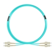
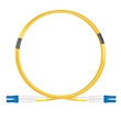
Comprehensive comparison of single-mode fiber (SMF) and multimode fiber (MMF)

- Introduction
- Comparison between single-mode fiber (SMF) and multimode fiber (MMF)
- What are the commonly used connectors on the market?
- The commonly used cladding materials for single-mode fiber (SMF) and multimode fiber (MMF) in the market
- The commonly used coating materials for single-mode fiber (SMF) and multimode fiber (MMF) in the market
- How to solve the signal dispersion problem of single-mode fiber (SMF) and multimode fiber (MMF)?
- Recommendations for fiber optic installation and maintenance
- Further Developments
- Note
- Frequently Asked Questions(FAQs)
- Q1: Can I use single-mode fiber (SMF) for short-distance transmissions?
- Q2: Can I mix single-mode fiber (SMF) and multimode fiber (MMF) in the same network?
- Q3: Which fiber type should I choose for my data center?
- Q4: What are the considerations for fiber optic cable management in a data center or telecom facility?
- Q5: How are fiber optic cables repaired in case of damage or breakage?
- Q6: How do fiber optic cables compare to traditional copper cables in terms of performance and reliability?
- Q7: What is dispersion in fiber optics, and how does it affect signal transmission?
- Q8: What are the key parameters to consider when selecting fiber optic cables for a specific application?
- Q9: What are the different types of fiber optic connectors commonly used?
- Q10: What type of light sources are commonly used with single-mode fiber (SMF) and multimode fiber (MMF)?
- Conclusion
- Contact Us
Introduction
In the world of fiber optics, two commonly used types of cables are single-mode fiber (SMF) and multimode fiber (MMF). These cables serve as the backbone of modern communication networks, enabling high-speed data transmission over long distances. In this blog post, we will delve into the characteristics, definitions, compatibility, and workings of both SMF and MMF. Additionally, we will compare various aspects including speed, bandwidth, application scenarios, and pricing. Let's explore the world of fiber optics in detail.
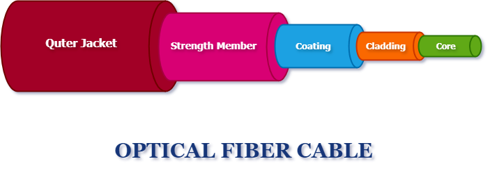
Single-mode Fiber (SMF)
Definition
Single-mode fiber (SMF) is an optical fiber that allows the transmission of a single mode of light, typically with a core diameter of 9 microns. It uses a laser as the light source, resulting in a narrow beam of light that travels in a straight line.
Characteristics
- Long Transmission Distance:
SMF offers long-distance transmission capabilities, reaching tens or even hundreds of kilometers without significant signal degradation.
- High Bandwidth:
Due to its small core size, SMF provides high bandwidth capacity, allowing for the transmission of large amounts of data.
- Compatibility:
SMF is compatible with various optical devices and systems, making it suitable for a wide range of applications.
- Cost:
SMF tends to be more expensive than MMF due to its specialized design and the need for precision connectors and equipment.
- Long Transmission Distance:
Multimode Fiber (MMF)
Definition
Multimode fiber (MMF) is an optical fiber that allows multiple modes of light to propagate simultaneously. It typically has a larger core diameter of 50 or 62.5 microns, enabling multiple light beams to travel through the fiber.
Characteristics
- Shorter Transmission Distance:
MMF is suitable for shorter distance transmissions, typically spanning a few kilometers.
- Lower Bandwidth:
Compared to SMF, MMF has lower bandwidth capacity due to the larger core size, resulting in limitations on data transmission rates.
- Compatibility:
MMF is widely used in local area networks (LANs) and data centers, where shorter distance transmissions are common.
- Cost:
MMF is generally more cost-effective than SMF, making it a preferred choice for short-range applications.
- Shorter Transmission Distance:
Comparison between single-mode fiber (SMF) and multimode fiber (MMF)
- Speed:
SMF supports higher data transmission rates, typically up to 100 Gbps and beyond, while MMF is commonly used for speeds up to 10 Gbps.
- Bandwidth:
SMF provides higher bandwidth capacity, allowing for the transmission of larger amounts of data over longer distances. MMF has lower bandwidth capacity compared to SMF.
- Application Scenarios:
Due to its higher bandwidth and transmission distance capabilities, SMF is commonly used in long-distance communications, such as metropolitan area networks (MANs), wide area networks (WANs), and intercontinental connections. MMF is typically used in short-distance communications, such as data centers, local area networks (LANs), video transmission, and sensor networks.
- Pricing:
SMF is generally more expensive than MMF due to its advanced technology and specialized applications. MMF is more cost-effective, making it suitable for budget-conscious projects.
- Light Sources and Receivers:
SMF typically requires narrow-spectrum light sources, such as lasers, to ensure single-mode propagation of light. MMF can utilize light sources with wider spectral widths, such as light-emitting diodes (LEDs). The narrow spectral characteristics of SMF enable higher signal transmission rates and lower losses.
- Dispersion:
Dispersion refers to the signal distortion caused by different frequencies of light signals propagating at different velocities in the fiber. Due to the concentration of light within the core, SMF exhibits lower dispersion, enabling support for higher bandwidth and longer transmission distances. MMF, on the other hand, introduces more dispersion due to the presence of multiple transmission modes and different optical paths, limiting its transmission distance and bandwidth capacity.
- Speed:
What are the commonly used connectors on the market?
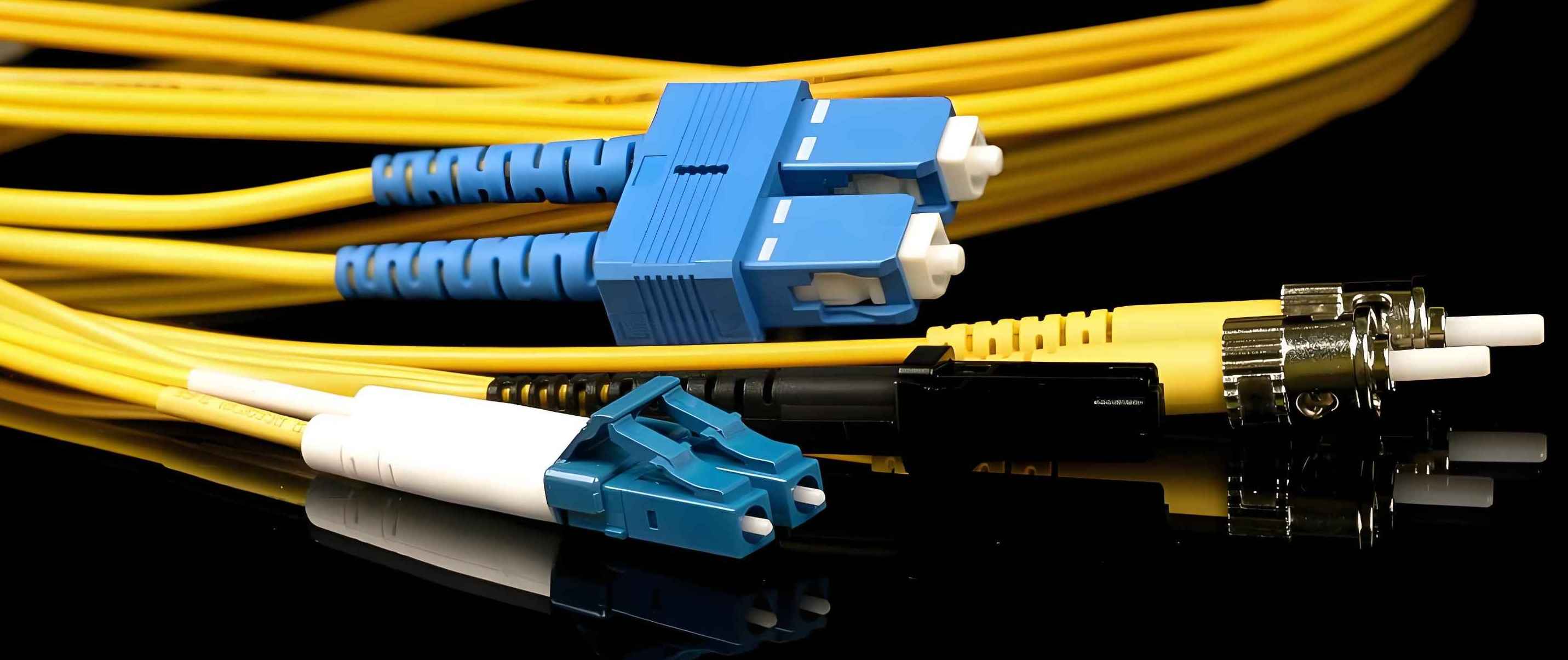
Single-Mode Fiber (SMF) Connectors
- SC (Subscriber Connector) connector
- LC (Lucent Connector) connector
- FC (Ferrule Connector) connector
- ST (Straight Tip) connector
Multimode Fiber (MMF) Connectors
- SC (Subscriber Connector) connector
- LC (Lucent Connector) connector
- ST (Straight Tip) connector
- MTRJ (Mechanical Transfer Registered Jack) connector
- MT-RJ (Mechanical Transfer-Registered Jack) connector
- SMA (SubMiniature version A) connector
These connectors are widely used for both single-mode fiber (SMF) and multimode fiber (MMF) applications in order to provide reliable fiber optic connections and transmission performance. The choice of connector type depends on factors such as the fiber optic connection environment, equipment compatibility, and specific application requirements.
The commonly used cladding materials for single-mode fiber (SMF) and multimode fiber (MMF) in the market
Common cladding materials for single-mode fiber (SMF)
- Silica:
Silica (SiO2) is the most commonly used cladding material for single-mode fiber (SMF). It has excellent optical properties and chemical stability, effectively confining the optical signal within the fiber core and reducing signal attenuation and dispersion.
- Silica:
Common cladding materials for multimode fiber (MMF)
- Silica:
Silica is also the most commonly used cladding material for multimode fiber (MMF). Similar to single-mode fiber (SMF), silica cladding restricts the propagation of light signals in multimode fiber (MMF), reducing signal attenuation and mode dispersion.
- Polymers:
In some specific applications of multimode fiber (MMF), such as short-distance communication and sensing, polymer materials such as polymers or fluoropolymers are also used as cladding materials. These materials have lower refractive index, allowing for larger mode diameters to accommodate multiple optical modes.
- Silica:
The differences between these cladding materials can be summarized as follows
- Refractive index:
The refractive index of the cladding material determines the propagation speed of light signals in the fiber and the numerical aperture of the fiber. Silica cladding has a higher refractive index, suitable for single-mode fiber (SMF) and high numerical aperture multimode fiber (MMF). Polymer cladding materials typically have lower refractive indices, suitable for large mode diameter multimode fiber (MMF).
- Transmission characteristics:
TDifferent cladding materials can affect the transmission characteristics of light signals. Silica cladding provides lower attenuation and dispersion in single-mode fiber (SMF), making it suitable for long-distance transmission and high-speed communication. Cladding materials for multimode fiber (MMF) have different transmission characteristics, depending on the specific application requirements for short-distance communication and low-speed data transmission.
- Manufacturing cost:
The manufacturing cost of different cladding materials can vary. Silica, as a commonly used material, has lower manufacturing costs and higher reliability. Polymer materials may require more complex manufacturing processes and have higher costs.
- Refractive index:
The commonly used cladding materials for single-mode fiber (SMF) and multimode fiber (MMF) include silica and polymers. The choice of cladding material should consider the fiber's application requirements, transmission characteristics, and cost.
The commonly used coating materials for single-mode fiber (SMF) and multimode fiber (MMF) in the market
Common coating materials for single-mode fiber (SMF)
- Acrylate:
Acrylate is a commonly used coating material for single-mode fiber (SMF). It provides mechanical protection to the fiber and helps in preventing damage from bending or environmental factors.
- UV-cured acrylate:
UV-cured acrylate coating is applied to single-mode fibers (SMF) and then cured using ultraviolet light. This coating offers enhanced protection and durability compared to regular acrylate.
- Acrylate:
Common coating materials for multimode fiber (MMF)
- Acrylate:
Acrylate coating is also used for multimode fiber (MMF), similar to single-mode fiber (SMF). It provides mechanical protection and helps in maintaining the fiber's integrity.
- Dual acrylate:
Dual acrylate coating involves applying two layers of acrylate coating to the multimode fiber (MMF). This improves the mechanical strength and protection compared to a single layer of acrylate.
- Acrylate:
The differences between these coating materials are as follows
- Mechanical protection:
Both acrylate and UV-cured acrylate coatings provide mechanical protection to the fiber. UV-cured acrylate offers better resistance against bending and environmental factors, providing enhanced protection compared to regular acrylate.
- Durability:
UV-cured acrylate coating is generally more durable and resistant to abrasion, chemicals, and temperature fluctuations compared to regular acrylate coating.
- Manufacturing process:
UV-cured acrylate requires an additional UV curing step during the manufacturing process, making it slightly more complex compared to regular acrylate coating.
- Mechanical protection:
The commonly used coating materials for single-mode fiber (SMF) and multimode fiber (MMF) include acrylate and UV-cured acrylate. Acrylate provides mechanical protection, while UV-cured acrylate offers enhanced durability and resistance. The choice of coating material depends on the specific requirements of the fiber application and the desired level of protection and durability.
How to solve the signal dispersion problem of single-mode fiber (SMF) and multimode fiber (MMF)?
Single-Mode Fiber (SMF)
- Dispersion-Shifted Fiber:
Dispersion-shifted fibers are designed to minimize chromatic dispersion by shifting the zero-dispersion wavelength away from the operating wavelength. This helps in reducing the dispersion effects and allows for long-distance transmission with minimal signal degradation.
- Dispersion-Compensating Fiber:
Dispersion-compensating fibers are used in conjunction with single-mode fibers (SMF) to offset the chromatic dispersion. These fibers have a higher dispersion value with an opposite sign, effectively compensating for the dispersion that occurs in the transmission fiber.
- Fiber Bragg Gratings:
Fiber Bragg gratings are periodic structures created in the core of the fiber. They are designed to reflect specific wavelengths while transmitting others, allowing for dispersion compensation by reflecting and manipulating the dispersion characteristics of the transmitted signal.
- Dispersion-Shifted Fiber:
Multimode Fiber (MMF)
- Graded-Index Fiber:
Graded-index multimode fibers (MMF) have a refractive index profile that gradually decreases from the center of the core towards the cladding. This design helps in reducing modal dispersion by allowing different modes to travel at similar speeds, minimizing the dispersion effects.
- Modal Dispersion Control:
Modal dispersion in multimode fibers (MMF) can be controlled by using mode-selective couplers or mode filters. These devices help in selectively transmitting specific modes and reducing the impact of modal dispersion on the signal quality.
- Higher-Bandwidth Fibers:
The use of higher-bandwidth multimode fibers (MMF), such as OM4 or OM5 fibers, can mitigate the effects of modal dispersion. These fibers have better modal properties, allowing for higher data rates and longer transmission distances.
- Graded-Index Fiber:
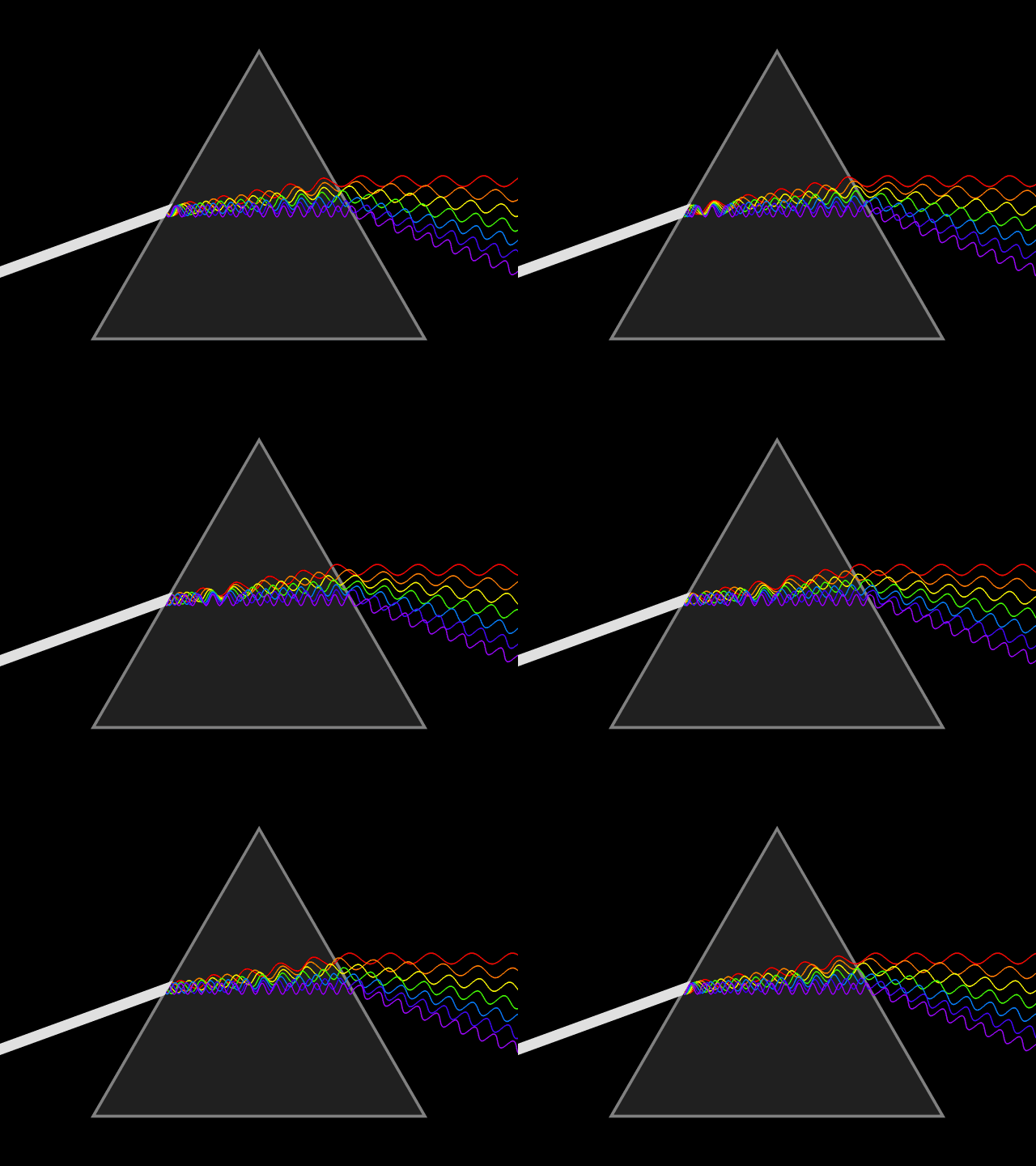
For modern glass optical fiber, the maximum transmission distance is limited not by direct material absorption but by dispersion, the spreading of optical pulses as they travel along the fiber. Dispersion limits the bandwidth of the fiber because the spreading optical pulse limits the rate which pulses can follow one another on the fiber and still be distinguishable at the receiver. Dispersion in optical fibers is caused by a variety of factors.
Reference Sources:Dispersion
In summary, signal dispersion in single-mode fiber (SMF) can be addressed through dispersion-shifted fibers, dispersion-compensating fibers, and fiber Bragg gratings. For multimode fiber (MMF), graded-index fibers, modal dispersion control techniques, and higher-bandwidth fibers are employed to mitigate dispersion effects. These approaches help in improving the quality and reach of optical signal transmission in both single-mode fiber (SMF) and multimode fiber (MMF).
Recommendations for fiber optic installation and maintenance
Installation
- Plan and Design:
Before installation, carefully plan and design the fiber optic network, considering factors such as cable routing, distances, connectors, and equipment requirements.
- Proper Cable Handling:
Handle fiber optic cables with care to prevent bending, twisting, or excessive tension that could damage the fibers. Use cable management solutions to organize and protect the cables.
- Connector Cleaning:
Ensure connectors are clean before installation. Use lint-free wipes and approved cleaning solutions to remove dust, dirt, and oils from connector end faces. Avoid touching the cleaned surfaces.
- Cable Labeling:
Label fiber optic cables for easy identification and troubleshooting. Use durable and legible labels to mark cables at both ends.
- Cable Bend Radius:
Adhere to recommended bend radius specifications to prevent signal loss or fiber damage. Avoid exceeding the specified minimum bend radius during installation and routing.
- Plan and Design:
Testing and Inspection
- End-to-End Testing:
Conduct thorough testing of the fiber optic link after installation to verify its performance. Use appropriate testing equipment, such as optical power meters and OTDRs (Optical Time Domain Reflectometers).
- Connector Inspection:
Regularly inspect connector end faces for any signs of contamination, scratches, or damage. Use fiber inspection scopes or video microscopes to ensure optimal connector cleanliness and quality.
- Continuity Checks:
Perform continuity checks using visual fault locators (VFLs) or fiber tracers to detect any breaks, bends, or faulty connections in the fiber optic link.
- End-to-End Testing:
Environmental Considerations
- Temperature and Humidity:
Ensure that the fiber optic cables and equipment are installed in an environment within the recommended temperature and humidity ranges to prevent signal degradation or equipment failure.
- Protection from Physical Damage:
Protect fiber optic cables from physical damage caused by sharp objects, excessive pulling or bending, and exposure to excessive vibrations or impacts.
- Dust and Contamination:
Keep fiber optic connectors and equipment free from dust, dirt, and other contaminants that can affect signal quality. Use dust caps to protect unused connector ports.
- Temperature and Humidity:
Regular Maintenance
- Cleaning Schedule:
Establish a regular cleaning schedule for connector end faces and equipment to maintain optimal performance. Follow manufacturer guidelines for cleaning frequency and methods.
- Documentation and Records:
Maintain detailed documentation of the fiber optic network, including cable routes, splicing points, and equipment configurations. Keep records of maintenance activities and any changes made to the network over time.
- Training and Certification:
Ensure that personnel responsible for fiber optic installation and maintenance receive proper training and certification to handle fiber optic equipment and perform necessary tasks correctly.
- Cleaning Schedule:
Upgrades and Expansion
- Future-Proofing:
Consider future bandwidth requirements and potential technology advancements when designing and installing a fiber optic network. Opt for higher-capacity cables and equipment to accommodate future upgrades without major infrastructure changes.
- Scalability:
Ensure that the fiber optic network design allows for easy scalability and flexibility to accommodate future growth or changes in network demands.
- Future-Proofing:
Remember, it is essential to follow manufacturer guidelines and industry best practices when it comes to fiber optic installation and maintenance. Regular inspections, cleaning, and testing will help ensure the long-term performance and reliability of your fiber optic network.
Further Developments
With advancements in technology, new fiber optic standards and techniques continue to emerge. For example, high-bandwidth single-mode fibers (SMF) such as ITU-T's G.654 and G.652.D can support higher data transmission rates and longer transmission distances. Additionally, the evolution of multimode fiber (MMF) includes new multimode fiber (MMF) standards such as OM3, OM4, and OM5 to support higher bandwidth requirements.
Note
It's worth mentioning that there are different generations and classifications of fiber optic cables within each fiber type, such as OS1, OS2, OM1, OM2, OM3, OM4,and OM5, which offer varying performance characteristics and specifications.
Frequently Asked Questions(FAQs)
Q1: Can I use single-mode fiber (SMF) for short-distance transmissions?
A1: While it is possible to use single-mode fiber (SMF) for short distances, it is more cost-effective to use multimode fiber (MMF) for such scenarios. Single-mode fiber (SMF) is better suited for long-distance transmissions.
Q2: Can I mix single-mode fiber (SMF) and multimode fiber (MMF) in the same network?
A2: Yes, it is possible to mix both fiber types within a network. However, the compatibility of optical devices and the use of appropriate connectors and transceivers should be ensured.
Q3: Which fiber type should I choose for my data center?
A3: For data centers, multimode fiber (MMF) is commonly used due to its cost-effectiveness and compatibility with short-range transmissions. However, if the data center requires long-distance connectivity, single-mode fiber (SMF) may be a better choice.
Q4: What are the considerations for fiber optic cable management in a data center or telecom facility?
A4: Fiber optic cable management in data centers or telecom facilities involves proper routing, labeling, and organization of the cables to ensure ease of maintenance, minimize signal loss, and prevent cable damage. It includes using cable trays, racks, patch panels, fiber enclosures, and proper cable strain relief techniques.
Q5: How are fiber optic cables repaired in case of damage or breakage?
A5: Repairing fiber optic cables typically involves identifying the damaged section, cutting it out, and splicing the remaining ends together using fusion splicing techniques. In some cases, if the damage is near the connector, it may be more practical to replace the entire cable or connector assembly.
Q6: How do fiber optic cables compare to traditional copper cables in terms of performance and reliability?
A6: Fiber optic cables offer several advantages over traditional copper cables, including higher bandwidth capacity, faster data transmission rates, immunity to electromagnetic interference, and longer transmission distances without significant signal degradation. They are also less prone to signal loss and are more secure against wiretapping.
Q7: What is dispersion in fiber optics, and how does it affect signal transmission?
A7: Dispersion refers to the spreading or broadening of optical signals as they travel through the fiber. Chromatic dispersion and modal dispersion are two common types. Chromatic dispersion occurs due to different colors (wavelengths) of light traveling at different speeds, limiting the achievable data rates. Modal dispersion occurs in multimode fibers (MMF) due to the different paths taken by the various light modes, causing signal distortion and limiting transmission distances.
Q8: What are the key parameters to consider when selecting fiber optic cables for a specific application?
A8: When selecting fiber optic cables, important parameters to consider include the fiber type (single-mode or multimode), core size, bandwidth capacity, attenuation, operating wavelength, cable construction (loose tube, tight-buffered, etc.), connector type, environmental rating, and compatibility with the intended network equipment.
Q9: What are the different types of fiber optic connectors commonly used?
A9: Some commonly used fiber optic connectors include SC (Subscriber Connector), LC (Lucent Connector), ST (Straight Tip), FC (Ferrule Connector), and MPO (Multi-Fiber Push-On) connectors. Each connector type has its own design, size, and suitability for specific applications.
Q10: What type of light sources are commonly used with single-mode fiber (SMF) and multimode fiber (MMF)?
A10: Single-mode fiber typically uses narrower-spectrum light sources such as laser diodes, while multi-mode fiber can use wider-spectrum light sources such as light-emitting diodes (LEDs).
Conclusion
Single-mode and multimode fiber (MMF) optics are two essential components of modern communication networks. Understanding their characteristics, definitions, compatibility, and applications can help in making informed decisions when it comes to selecting the appropriate fiber type for specific scenarios. Whether it's long-distance transmissions or short-range connectivity, fiber optics will continue to revolutionize the way we communicate in the digital age.
Contact Us
If you have any further questions or require more specific information, feel free to ask! info@flypro.com


